Laplanda Multi-Modal Optical Diagnostic & Characterization Station
- Summary
Automated, nano-precision optical diagnostics platform designed to characterize structural profiles, thermal responses, and localized spectral properties of a target material/substrate. Using an ultra-stable 450nm Distributed Feedback (DFB) laser system, the setup precisely transitions between three distinct analysis positions to perform high-resolution optical profiling and monitoring.
- Platform Core Parameters
- Primary Light Source: 450 nm Wavelength (WL) Distributed Feedback (DFB) laser diode.
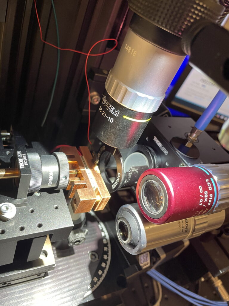
- Fiber Coupling Interface: Integrated single-mode alignment array leveraging a Thorlabs HCS013 RMS-threaded flexure mount stage.
- Mechanical Positioning Resolution: 100 nanometers (nm) active linear step resolution across X-Y-Z planes.
- Thermal Management: Exposed high-purity segmented copper heatsink mount blocks for structural anchoring and thermal dissipation.
- Multi-Position Multi-Modal Workflow
Position 1: Near-Field Optical Profiling
- Objective: Capture high-resolution spatial details of the emitted/transmitted light field.
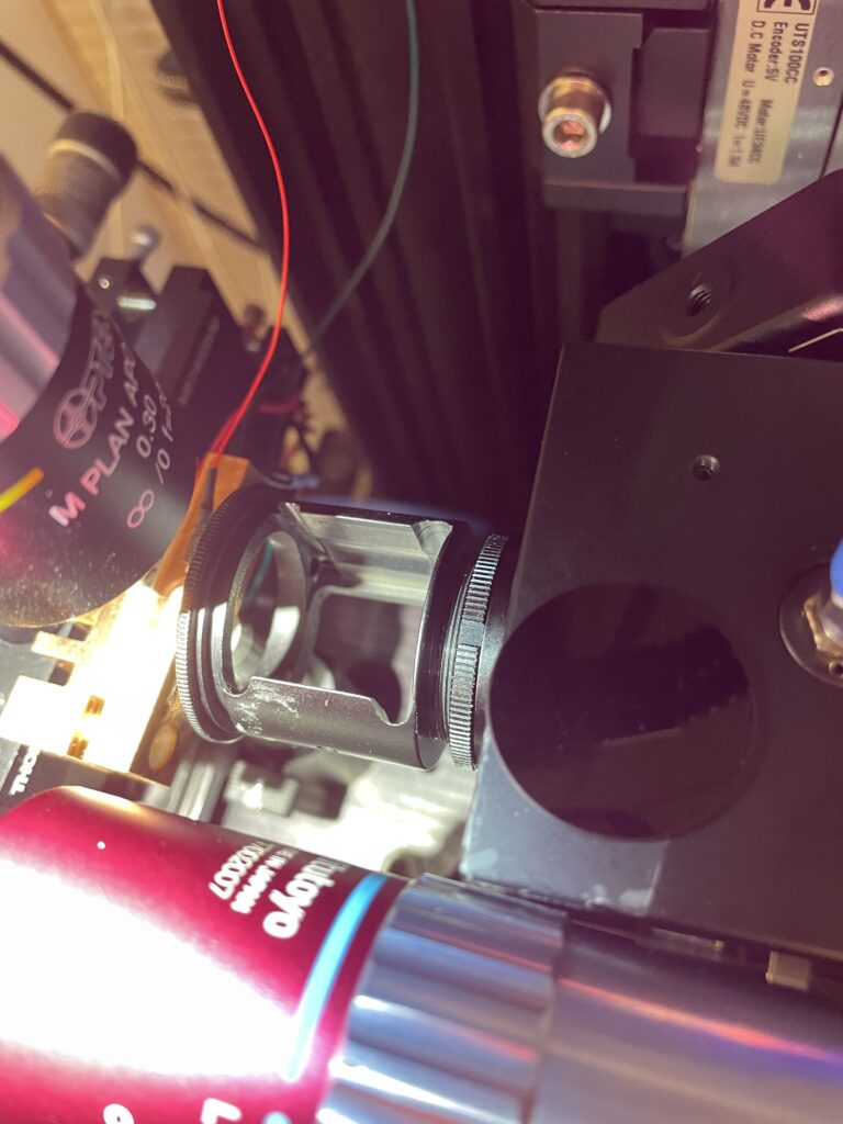
- Mechanism: Relies on a high-numerical-aperture (High-NA) microscope objective lens system to capture and project a heavily magnified near-field distribution profile.
- Data Output: High-resolution spatial beam tracking and localized optical density metrics.
Position 2: Transient Thermal (Infrared) Evaluation
- Objective: Monitor localized thermal stress and temperature degradation over exact illumination windows.
- Mechanism: Shifting focus to an integrated mid-wave or long-wave Infrared (IR) thermal camera aimed at the substrate target.
- Data Output: Continuous surface-temperature plotting, thermal drift curves, and heat-map video over extended exposure times.
Position 3: Localized Spectral Characterization
- Objective: Map the physical emission shift, absorption metrics, or optical degradation across the 450nm DFB laser interaction region.
- Mechanism: Direct coupling of localized light output to a multi-channel optical spectrometer interface.
- Data Output: 3D hyper-spectral mapping profile and narrow-band peak wavelength drift monitoring.
- Optical Alignment & Mechanical Constraints
Thermal Sink Interference: Optical access clearway must exist through the copper block dividers to prevent structural shadowing during IR thermal camera steps.
Backlash Mitigation: Closed-loop piezo actuators or ultra-fine pitch micrometers to maintain strict 100nm step boundaries without mechanical drift.