High frequency domain amplification and analysis
The measurement technique for high-frequency characterization is addressed. The method created is a characterization of the frequency-domain amplification and analysis. Two approaches employed as a frequency-domain analysis of circuits and its roots in analogue system design. Time-domain analysis is integrated for digital IC-design. It will be shown that frequency- and time-domain analyzers deliver compatible and complimentary results. The instrument described in this chap and can measure the black-box description or signal integrity characteristics of a package or interconnection under test.
For the measurement of an impedance, the LCR (inductance-capacitance-resistance) or impedance instrument is used. The instrument delivers a time-harmonic voltage over the access port of the device under test and measures the amplitude and phase of the current in the port. By dividing the voltage by the current, the input impedance at the port is obtained. To reduce inaccuracies, four-terminal measurements are performed.
By using independent signal current paths and voltage sensing cables, the effect of the measurement wire impedance is reduced. Coaxial cables provide a minimal stray capacitance. Moreover, by using coaxial cables, the mutual coupling problem of the wires can be solved. In the case of a DDT impedance smaller than 1 Q and if one uses single wires, a large current can flow through the current path creating a mutual coupling to the voltage sensing wire. With the set-up of figure below, impedance values from mQ to MQ can be accurately measured.
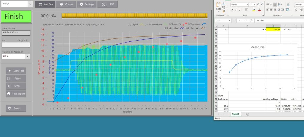
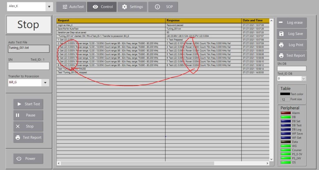
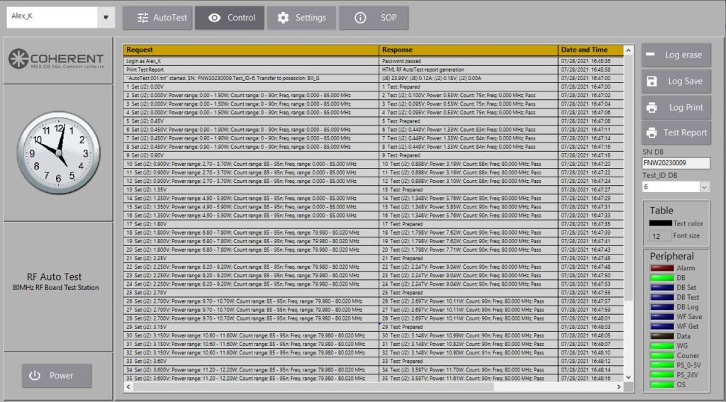
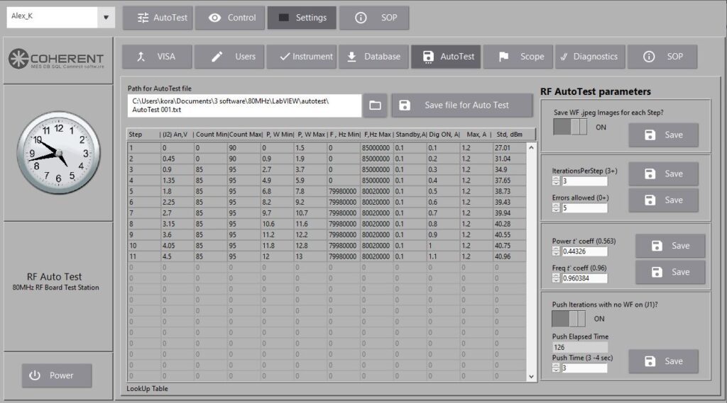
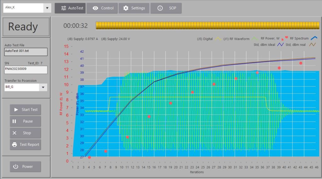
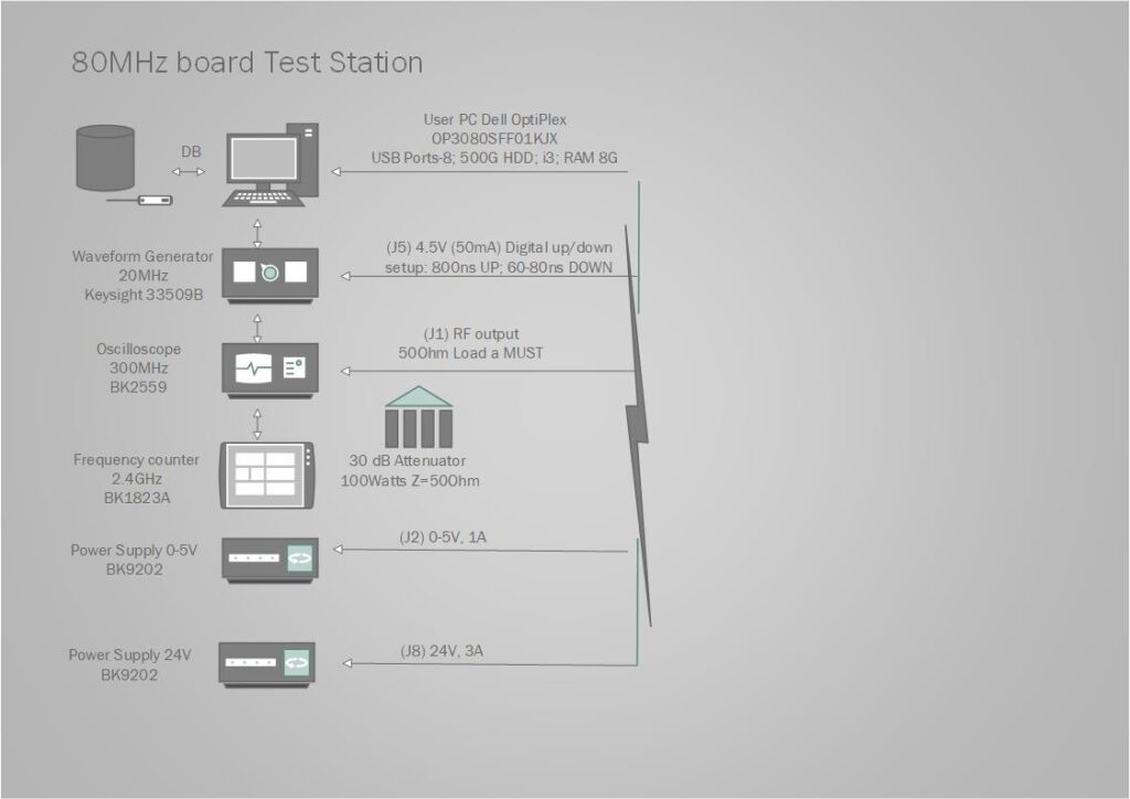
The GUI is used: Control of acquired data is performing by automatically generated derivatives: