Тhe collection of programs, data, and instructions that enable computers and other devices to perform specific tasks. It includes the tools, methods, and knowledge used for developing, operating, and maintaining software and software-intensive systems.
Laplanda_MES_SQL_Connectivity Software
Manufacturing Execution System (MES) with SQL (Structured Query Language) Database Connectivity.
A Tier-3 architecture approach has been used to develop user interfaces and business services.
The SQL queries was used to develop the data services with approach to minimize rework when new modules is integrated into the MES. Eventually, a stronger coupling between test sets, production control applications and the MES is developed.
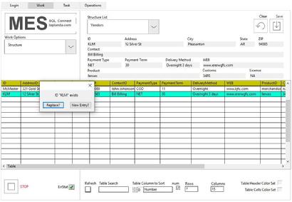
Our MES application is tracking the fabrication of each component. All relevant data is recorded (Temperature, technician ID, work center ID, time, procedure, out-of-specs components, defects, etc…) and can be retrieved to analyze defects and improve quality. Reporting is done using Crystal Report.
Purchase orders from customers are transformed into work orders and the production is tracked trough the MES.
The products and their bill of material (BOM) are defined in the database, along with the work centers and the travelers. Change requests are also managed by the system.
The solution is expendable, and the system may eventually include the Raw Material Treatment, Planning, Bidding, Invoicing, Procurement and Inventory Management modules.
The project initiated from the need of PDM to track Transfer Fab components and to replace its paper-based tracking processes. PDM wanted to keep and retrieve the fabrication history of every component and assembly product. PDM also wanted to set the corner stones of a production system that could grow with the company and increase the overall Fab productivity…
Laplanda_MES_SQL_Connect is all you need for conducting your business in effective and secure way.
Intragenomic Processor Alignment Software
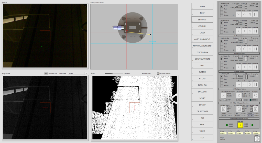
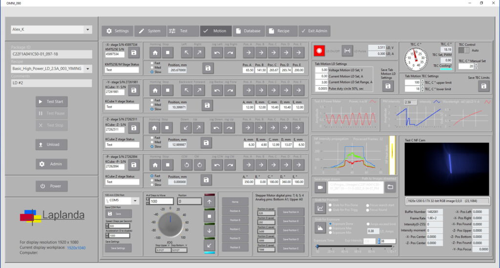
Intragenomic Processor basic alignment algorithm of test panel determined as an alignment marks positioning with camera exposure time calibration based on the intensity value range that is usually should not accede 255 and the tune it in range of >240:250<; focus adjustment for different magnification; XY and R tilt accordingly. Two alignment marks positions are saved for further work with the device under the test. This is the basic step with working with test panels, wafers, tapes or other devices under the test. Video is below.
Intragenomic Processor Alignment components.
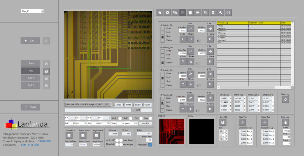
Intragenomic Processor alignment basic components include linear and rotational stages, drivers, controller, microscope(s), and light source for microscope that is usually provided by the fiber optics cable, high speed camera all placed on the stable substrate to prevent vibration. For effective alignments it is using Real-Time OS for the computer that is controlling the coordination between camera video processed values and the petitioners. Intragenomic Processor has DZ-2 microscope with auto focus adjustment mechanism. All controls are performing by Win OS PC; see short video of the alignment step.
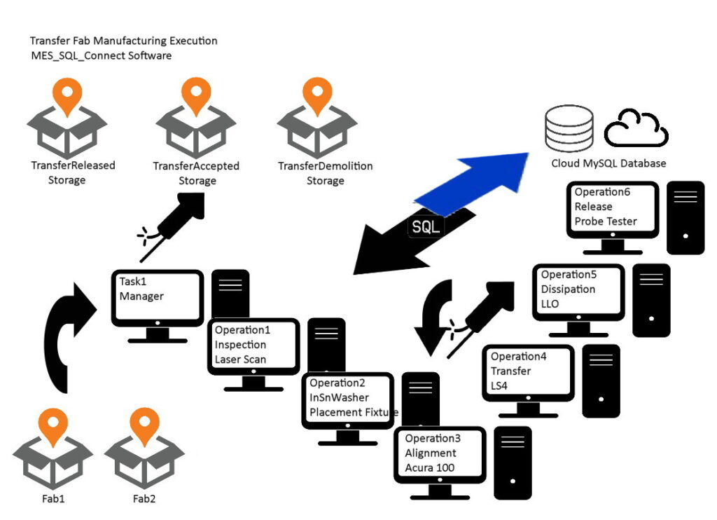
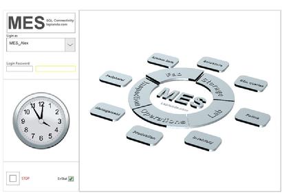
Laplanda_MES_SQL_Connect software
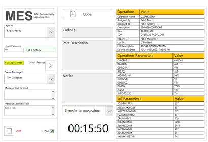
Laplanda_MES_SQL_Connect is a system for continuous process flow of the Fab. The diagram explains the basic operation steps and apparatus involved. Each station has LAN connection to the database for required data grabbing and report. The important part of the MES is the communication between operators in the same MES program GUI. Manager controls execution of the steps, create Tasks and Operation Procedure for each Process Step. Download Free and fully functional Laplanda_MES_SQL_Connect application here…
MLED Transfer Alignment Software GUI
To get the efficient alignment system for any type of the process it is require the next basic components:
• linear and rotational stages
• Drivers
• Controller
• Microscope(s)
• Light source by the fiber optics cable
• High speed camera
• Stable substrate to prevent vibration
For effective alignments it is using Real-Time OS for the computer that is controlling the coordination between camera video processed values and the petitioners.
Micro LED Transfer Technology: MLED Transfer System
Mass transfer is a critical technology for Micro LED manufacturing, transferring Micro LED to a target backplane quickly and accurately will be one of the topics that manufacturers need to work on the most as well as on improving UPH and yield. Micro LED technology are facing lots of technology challenge, there are four key technologies on Micro LED manufacturing, transfer technology takes the hardest part of manufacturing, however, driver IC, color conversion, inspection equipment and way of inspection, wafer wavelength uniformity, those are waiting for the technological bottleneck breakthrough. See the advanced MLED transfer tool video…
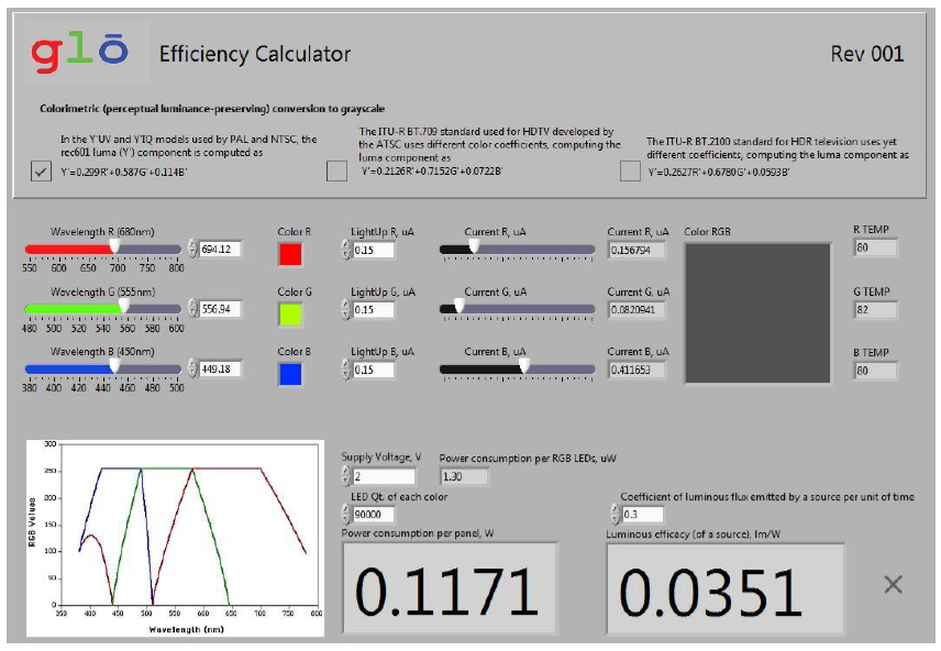
Efficiency Calculator
Power consumption per RGB Panel; RA 300X300 array. 90,000 LEDs per color.
Y-UV and Y IQ models: 0.1171 Wh
Micro LED Transfer device GUI – control
Micro LED Transfer device GUI includes the next control Tabs:
- Home
- Encoder and Driver
- Host and Real-Time OS PC
- CPU load
- Controls
- Structure
- Gamma and Digitizer
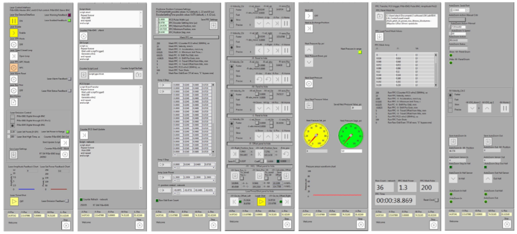
Micro LED Transfer device GUI – functions
- Micro LED Transfer device GUI includes the next functions Tabs:
- Laser control
- Digitizer commands
- PCO rules
- Motion control
- Vaccuum Nest control
- Process control
- Peripheral
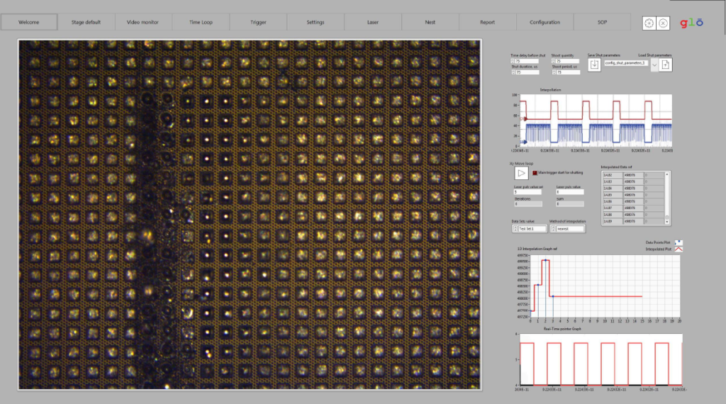
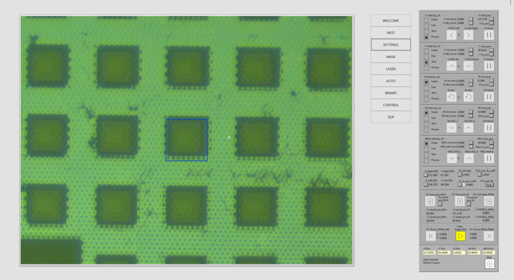
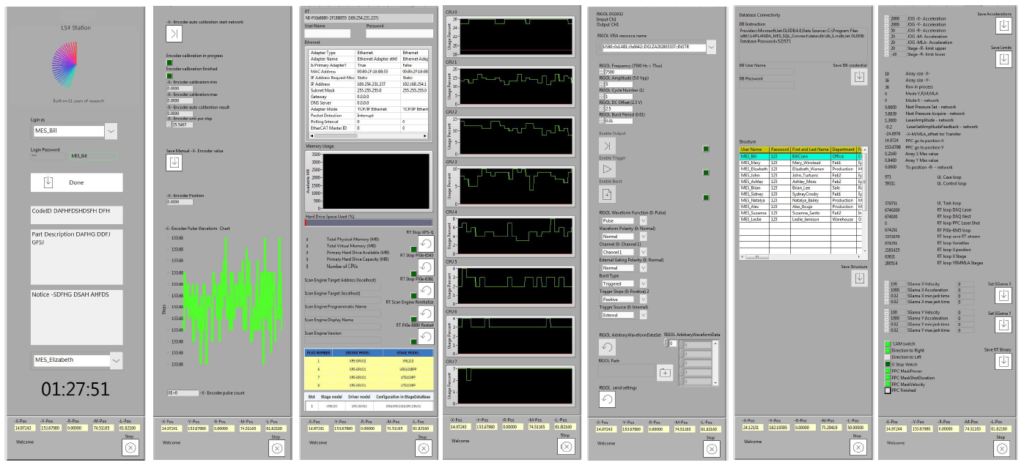
MLA-263 Station
MLA-263 Station Control Panel has the next functional Tabs: Welcome STANDBY, Stage Default the settings of the position of the X,Y,R,M,MLA stages for calibrations, saving and loading to and from the configuration file, training shut, HOME, MICROSCOP positioning, LASER positioning, fixed positioning for groups, wafer detection, auto focus, position window. Video Monitor Morphological and binary transformation, threshold, saving and uploading the result 2D images. Time Loop Real Time monitoring, Start the Loop, Characterization, Methods of interpolation, Saving the interpolated data, loop time parameters. Trigger Real Time timing, pulse duration, pulse interval, pulse amplitude, delays, interpolation data, tracing and feedback. Settings Stage parameters, Velocity, Acceleration, Positioner names and groups, loops frequency, buffer volumes, acquisition s peed. Laser single and continues shut control. Nest Wafer setting pressure control. Report time stamp, report the position versus shut, absorption index, timing, deviations, distortion, operator’s name. Configuration Real Time Tracing and Monitoring SOP.
LPLBA046 CW PW LD Test System
LPLBA046 is a system for full characterization of the Low (up to 5W) laser beam for CW and PW regime withing of 1-1GHz frequency domain. Measurement features: Optical Power; Spatial Aspects: Beam Profiles and Beam Quality; Withing different frequency components of a laser beam; M2 factor; Beam uniformity; Beam propagation; Beam peak intensity from the context of Gaussian beams; Beam pointing fluctuations; The polarization; Temporal and Spectral Aspects; For pulsed lasers, measurements of the pulse energy, pulse duration and peak power; Near Field (NF) profile; In the case of Q-switched lasers, optical energy; Spectrum and spectrum power; Adjusting Optical Attenuation and absorbing neutral density filters at high power.
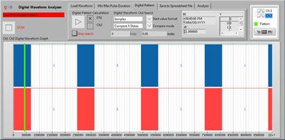
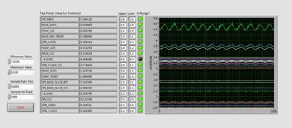
Digital Waveform Analyzer
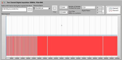
Digital Waveform Analyzer is performing the two-channel Acquisition, Search by required criteria and Analyze the Digital Waveform.
Two Channel Digital Acquisition up to 200MHz.
PXIe-6545.- RT software for NI PXIe-1071 slot NI PXIe-6545
Digital Waveform Analyzer
• Min Max Pulse duration with Indexes for lover and upper hysteresis levels.
• Search for Digital Pattern. – PC base HWS file loader and analyzer.
• Saving to the Spreadsheet file.
• Analysis of the pulse duration and comparison.
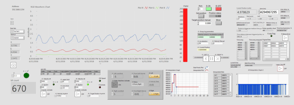
Nano Scanning setup and GUI
The method can be used for linearity, coordinate and shots following by scan trajectory.
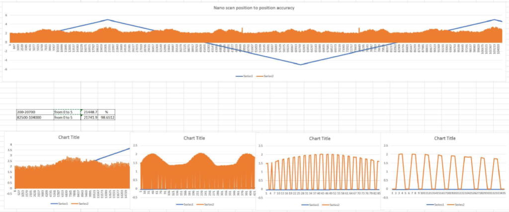
Nano Scan algorithm includes the the quantifying, intensity and duration of each individual shot.
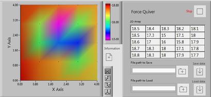
Force Quiver software
The drift of the depth of the surface is happens under different circumstances. The temperature, humidity, stress of material, applied force, stretching etc. To det the data of drift the Force Quiver software is created. The algorithm is getting the visualization of the processes in the surface flatness based on calculation of CRI indexes from each pixel and transforming it to the unit of force.
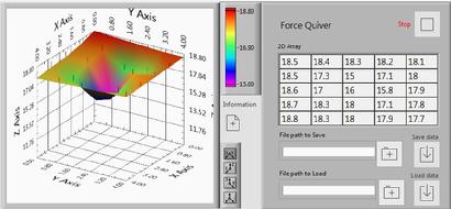
The area of the exploration is depending on the task and can vary from nm to any values. The convenient GUI representation give to the observer the full understanding of the processes to find the proper solution.
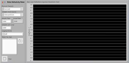
Wafer Reflectivity Meter.
Wafer reflectivity pattern is important for any type of laser applications. Wafer Reflectivity Meter technique is created in an order to collect and analyze the acquired reflective lite in blue 420 nm radiation spectrum. The precise movement require for repeatability and confirmation of the acquisition result. The Newport stages is used for accurate and fast 300 mm/s and acceleration 2500 mm/s/2.
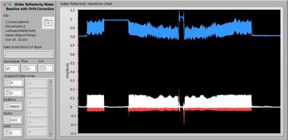
The source of the lite is the Blue Laser collimated to 30mm lens. The beam is passing BSX05 – Ø1/2″ 90:10 (R:T) UVFS Plate Beamsplitter for getting the reflection from the wafer. The data acquired is collected by PbS Amplified Photoconductive Detector and NI USB-6000 with the speed 10 kS/s. The Wafer Reflectivity Reader software allows to control and to save data to TDMS format. The Wafer Reflectivity Analyzer allows to represent the acquired data in human understandable format along the Baseline with Drift Correction.
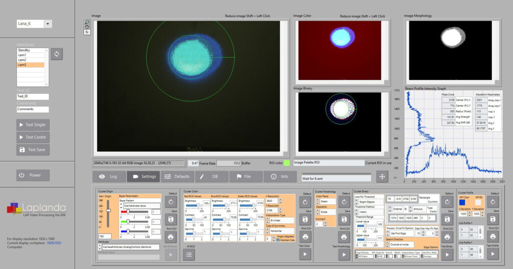
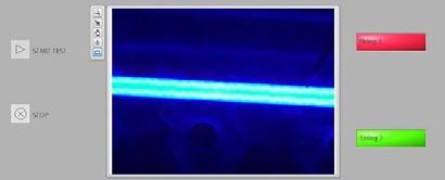
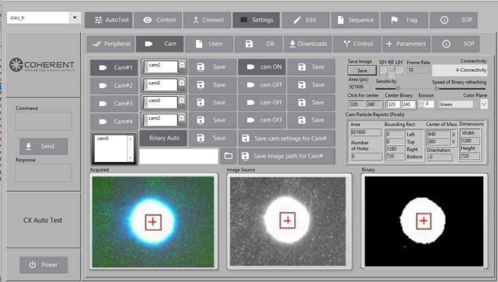
LAP Cam Laser Beam Video Processing and Report
Login to the system; camera status indicated by color (Green = ready, Orange = not configured). Save various image processing parameters (original, color transformation, morphological, binary). Configure camera settings, adjust parameters, and save configurations to config.ini. Use controls for starting tests, saving results, and managing test progress. Automated tests run across all connected cameras with options for continuous video processing. Log errors, auto-adjust settings, and generate reports with saved images and logs.
Candela Chrome CH317
The software performs the Vision analysis including histogram, HOG-LBP texture classification, line profile, SSIM; barcodes including Data Matrix Grading AIM DPM 2006, 1D barcode, Data Matrix code, PDF 417, QR code, unwrap barcode; binary analysis including binary morphological reconstruction to find particles, particle analysis report, particle filter; calibration including calibration models comparison, perspective calibration; edge detection; classification including color and particle classification;
CIE color distance, color matching, color pattern matching, color segmentation, color threshold, contour analysis, contour defect inspection; feature correspondence including corner and feature point detection, feature matching; AVI codec comparison, Read/Write AVI with data; geometric matching including geometric matching with calibration, match multiple geometric patterns; golden template comparison including template inspection; image processing including BCG lookup, flat field correction and estimation, gray morphological reconstruction (H-Dome), image label, image threshold, magic Wand, math lookup, morphological segmentation; light meter; motion estimation including optical flow feature tracking; OCR; image averaging, color pattern matching, auto report. Read more…
Barcodes reader and QR Label creator BCRC019
BCRC019 a linear and QR code reader and creator. A QR code (quick-response code) is a type of two-dimensional matrix barcode, invented in 1994, by Japanese company Denso Wave for labelling automobile parts. A barcode is a machine-readable optical image that contains information specific to the labelled item. In practice, QR codes contain data for a locator, an identifier, and a website visitor tracking. To efficiently store data, QR codes use four standardized modes of encoding (i) numeric, (ii) alphanumeric, (iii) byte or binary, and (iv) kanji.
Consumerer BR30 Test Bed Software
I2C interface, board revision 5020-000XX_REV01, board BMD-SRA-1-A-T_Rigado_7188-00011, ICS-43432_InvenSense_7183-07101, IRS-B210ST01-R1_Murata_7183-07100, SI1146-A10-GMR_Silicon Labs_7183-07202.
18 AI; 5 DIO; SPI
Ambient Fixture Package Tester
Ambient Fixture Luminous Emittance Tester software adds-on
•Detect individual LED problem
•Pass/Fail treshold
•Orientation location
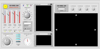
VIXEL-320 Control Panel
Controls XYZ microscope steppers for proprietary oxidation vertical-cavity surface-emitting laser’s glass mirroring station; control panel with USB interface for MFS. In-situ oxidation monitoring is done by an infrared optical microscope that is focused on VCSELs or oxidation test structures. oxidation progress control, stops either automatically at the maximum duration programmed, or by the operator when the desired aperture size is reached.
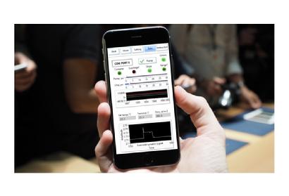
Remote controlled Candela 7055 Photonic Sequencer
Ultra Fast Photon Spectroscopy of the DNA fragment method is developed as a sequencing the data flow of RNA polymerase molecule per cell collected using fragmentation of spectrum wavelengths of reflection of the sugar AGTC in timeline and assigning the classification to it as a particles specified in filtered data array. The mobile device can be adopted for running of most of the functions.
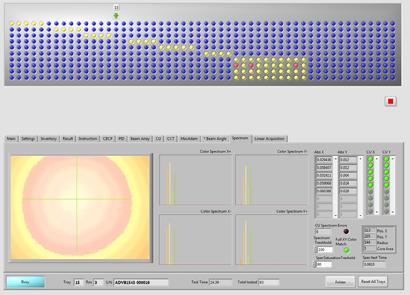
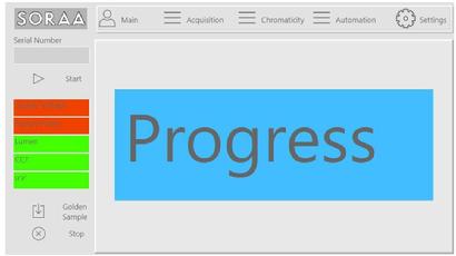
CBCP Stage of Production Lamp Hot Tester
System that allows to perform the testing of SORAA LED product in Arts environment. The goal of CBCP Stage of Production Lamp Hot Tester is to detect the parameters of CBCP, Beam Angle and CU for tested part and characterize this part for pass/fail criteria, to determine and to describe CCT, Spectrum and other parameters declared below and to create the report. Controls two step motors for linear motion and for Iris auto control, Stop Home sensors, Baster USB 3.0 camera, RGB sensors, temperature sensors and more.
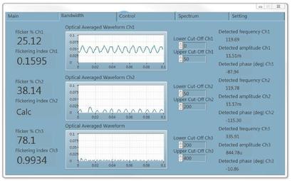
Candela-7308 Flicker Measurement Device software
- Flicker Perception of visual unsteadiness induced by a light stimulus whose luminance or spectral distribution fluctuates with time, for a static observer in a static environment. ~0-80Hz
- Phantom Array Perception of a spatially extended series of light spots when making a saccade (image transition across the retina) across a light source that fluctuates with time. ~50Hz-2kHz
- Stroboscopic Effects Change in motion perception induced by a light stimulus whose luminance or spectral distribution fluctuates with time, for a static observer in a non-static environment. ~50Hz-2kHz
- Temporal Light Artifact An undesired change in visual perception, induced by a light stimulus whose luminance or spectral distribution fluctuates with time, for an observer in a certain environment.
Sources of TLA
1. Source voltage changes (noise)
2. Externally coupled noise sources
3. Dimmer phase angle instabilities (when dimming)
4. Driver instabilities
5. Driver (intended) operation
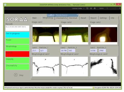
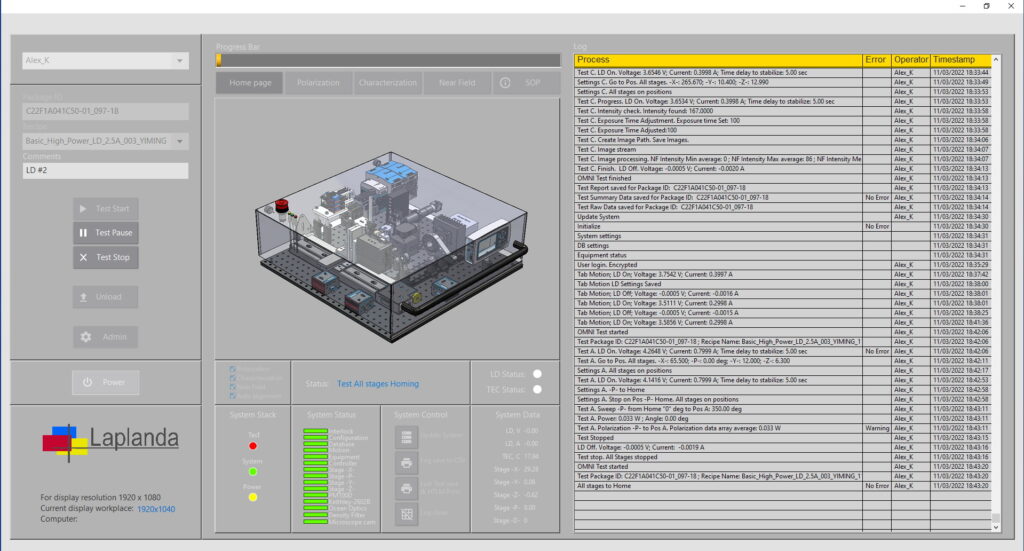
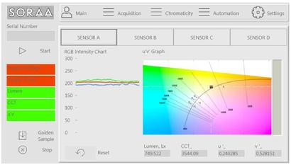
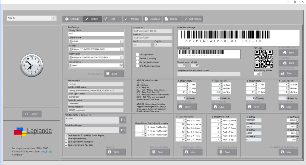
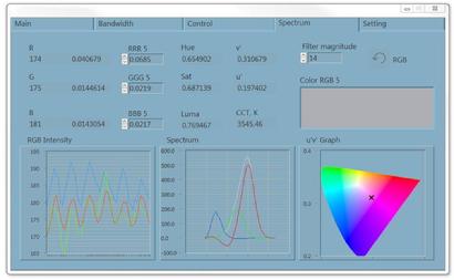
Candela-7314 Ambient Fixture Tester
- Ambient Fixture Tester is a device that performs the measurement of electrical parameters, comparison of Optical capacity, Intensity, Chromaticity with referenced values and is making a Morphological analysis.
- All hardware integrated in one enclosure with 7 fast USB 3.0 ports, with extension of two monitors with high resolution, with own touch screen 7″, controlled power with Emergency button, WI-FI and LAN internet, serial ports for acquisition sensors, and other [peripheral. The details about Candela hardware please search in Automation section
- Fast 2.8GH Intel processor allowed to perform the test with highest accuracy and precision.
- The ATmega ARM microcontroller programmed as a part of OS and integrated as an acquisition and control module.
- Own voltage and current acquisition allows to get the parameters of active voltage, current and power continuously
- The software is working as AI platform with minimum function from operator. The start of the test is begin when the tested part barcode is scanned.
- The All-In-One concept allows to minimize the wiring and reduce the size of the equipment.
- Windows 10 OS based software allows integrate most of the electronic measurement devices and make them a part of the test system
- Candela design is a future of local measurement systems . Please read more by linking below.
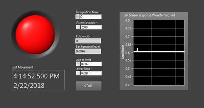
PIR Sensor Tester
A passive infrared sensor is an electronic sensor that measures infrared (IR) light radiating from objects in its field of view. PIR-based motion detectors Tester allows to detect the base parameters of timing and Lens shape for particular PIR.
High frequency domain amplification and analysis HFPT003
HFPT003 is addressed to the measurement technique for high-frequency characterization. The method created is a characterization of the frequency-domain amplification and analysis. Two approaches employed as a frequency-domain analysis of circuits and its roots in analogue system design. Time-domain analysis is integrated for digital IC-design. It will be shown that frequency- and time-domain analyzers deliver compatible and complimentary results. The instrument described in this chap and can measure the black-box description or signal integrity characteristics of a package or interconnection under test.
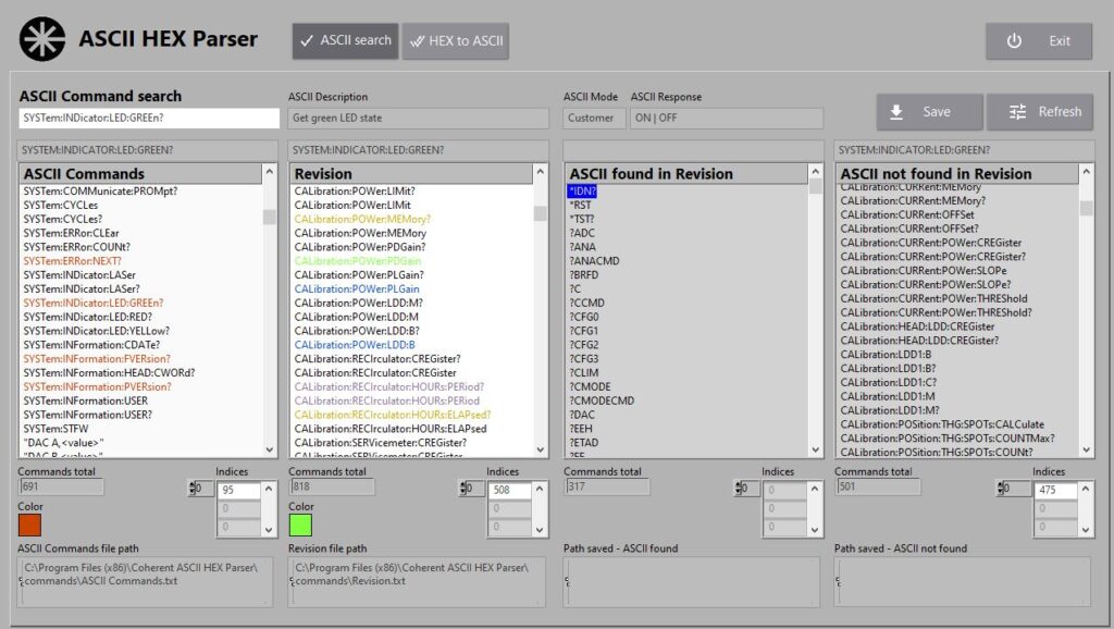
ASCII HEX Parser
Developers are eventually needed to look up hex or ASCII values and see what they translate to. But this is not for developers only. The technology goes forward, and the devices are changing the control methods. ASCII HEX Parser is a converter, searcher, comparator, decoder and error analyzer in one GUI.
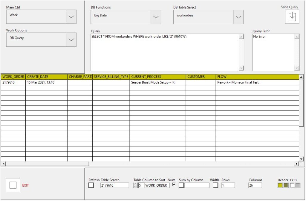
Laplanda Database measurement storage and analyzer LDB_MA
LDB_MA is a GUI that helps organize and keep data for the following analysis and performing to the new tasks. This tool is an Add-on to the Laplanda MES and can be employed as an independent product for digital warehouse needs
Laser Beam Analyzer LBA_023
Laser beam analyzer LBA_023 are used to determine the quality of a laser beam. Laser beam analyzers measure beam profile, average power, energy per pulse, frequency, and temporal pulse shape.
LBA_023 provides vital information on the quality of laser beam light. Laser quality is important for maintaining the precision of laser cutting and welding processes. A laser beam analyzer can be used as a diagnostic tool, monitoring the various laser beam parameters. LBA_023 comes with data storage and analysis software.
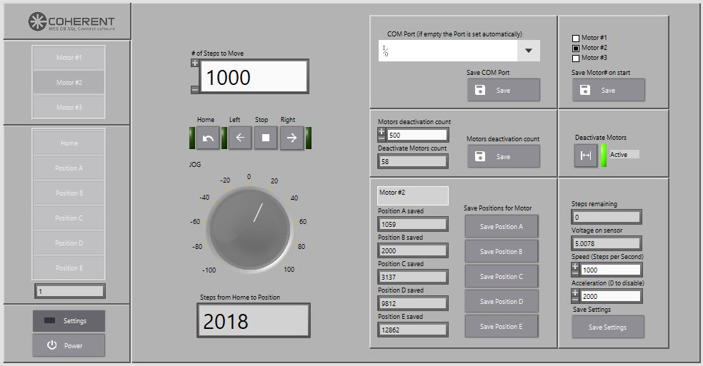
Motion control GUI
The effective and convenient motion control is made using micro linear stages (up to 20kg load horizontally and up to 2kg load vertically) and single motherboard computer. L298N Motor Driver Controller Board Module DC Dual H-Bridge for Arduino Smart Car Power UNO MEGA R3 Mega2560 is used. Touch screen monitor allows to control the stages move and its settings without a keyboard.
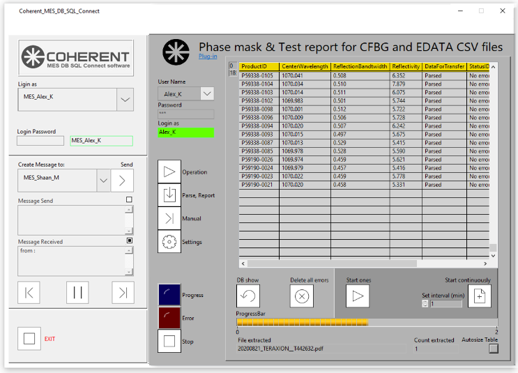
FTP Phase Mask Report embedded
To implement FTP data exchange and to embed it to the MES system the Laplanda Database Connect is perfectly fits.
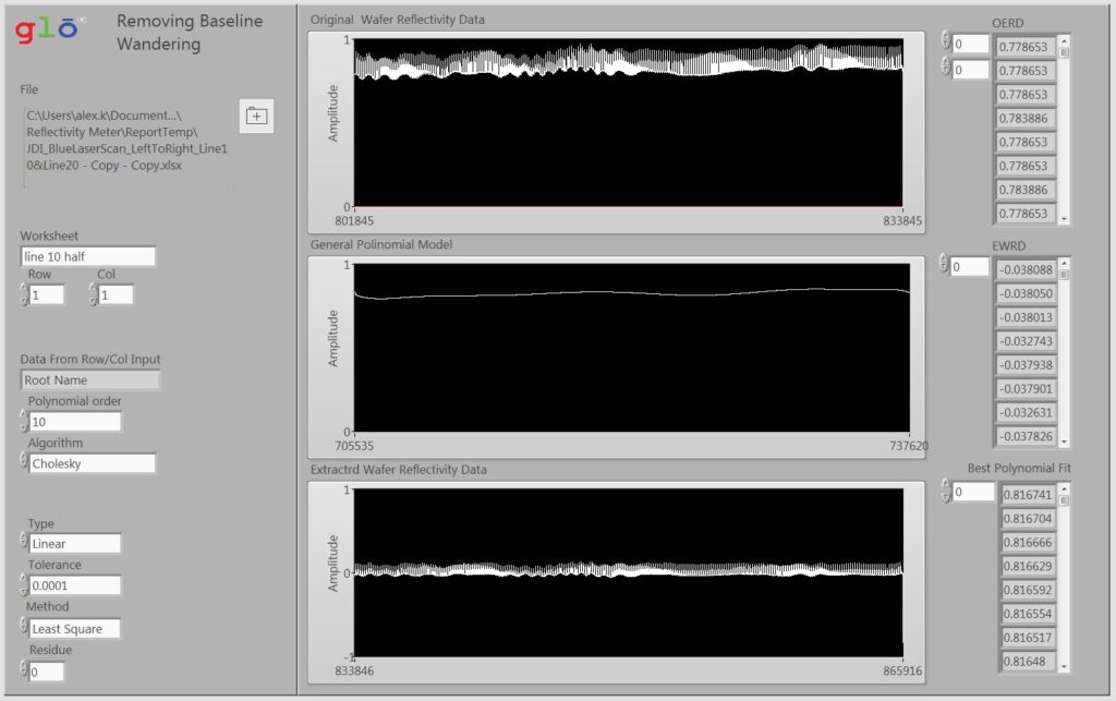
Removing Baseline Wandering technique
A new method for removing the baseline wander (BW) noise based on multivariate empirical mode decomposition is presented. The proposed method is compared with recently introduced technique for BW removal using Hilbert vibration decomposition in terms of correlation coefficient criterion and signal-to-noise ratio. To evaluate the performance of the proposed method, real BW signals are added to synthetic and clinical electrocardiogram (ECG) signals. It is shown that presented methodology has significant scope of removing BW noise in real world ECG signals.
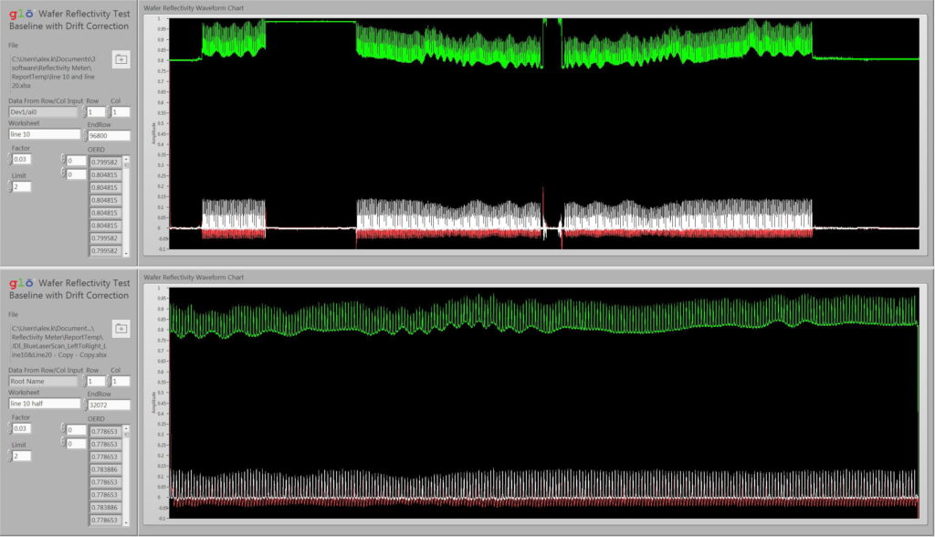
Wafer Reflectivity Test with Baselane Correction
The reflectivity method can be used in multiple application. The only the problem is the noise that needs to eliminate. The new invented method allows to reduce the noise effect on the test result.
High Speed Prober HSP087
The four point electrical probe is a very versatile method used widely in physics for the investigation of electrical phenomena. HSP087 has especially designed two four point superconducting devices from the YBa2Cu3O7 and the Bi2Sr2Ca2Cu3O10 materials for such investigations. The Complete Exploration Kit and the Super Exploration Kit contain four point electrical probes. Newport high resolution stages are used.
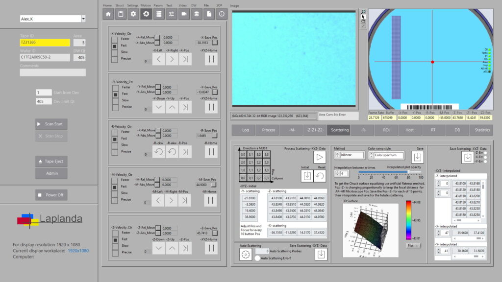
High Speed Scanner HSS147
HSS147 employed the new advanced technology of the flattering the researched surface by method of the Interpollated Scattering. This method allows to get the interpollation of -Z- point for each -XY- position of the surface. This helps to keep focus with maximum accuracy in the range of the focal distance. The independent microscope stages allows to create focus for the start position of the scan for each microscope in use.
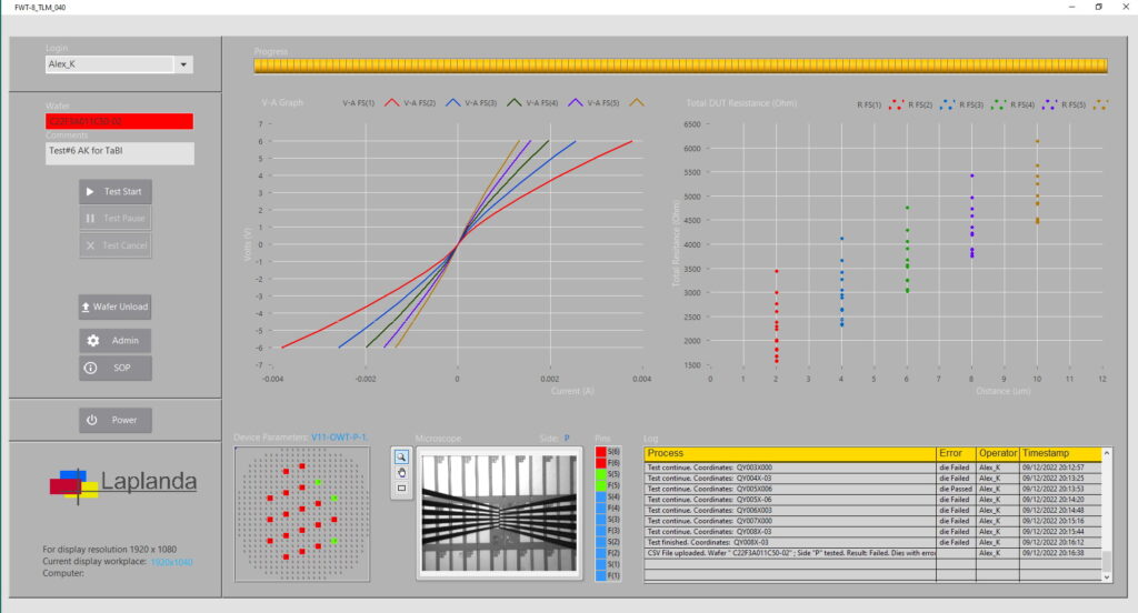
TLM Tester TLM115
TLM115 elimenate the effects of contact resistance during the Wafer test with the use of a four point probe. Four probes have been attached to the test sample. A constant current is made to flow the length of the sample through probes labeled F(1)S(1) with followed series of probes. For precise and fast result reading the Keithley instrument with PW function for short pulses (10us width) is used.
LPLBA046 CW PW Laser Test System
LPLBA046 is a system for full characterization of the Low (up to 5W) laser beam for CW and PW regime withing of 1-1GHz frequency domain. Measurement features: Optical Power; Spatial Aspects: Beam Profiles and Beam Quality; Withing different frequency components of a laser beam; M2 factor; Beam uniformity; Beam propagation; Beam peak intensity from the context of Gaussian beams; Beam pointing fluctuations; The polarization; Temporal and Spectral Aspects; For pulsed lasers, measurements of the pulse energy, pulse duration and peak power; Near Field (NF) profile; In the case of Q-switched lasers, optical energy; Spectrum and spectrum power; Adjusting Optical Attenuation and absorbing neutral density filters at high power.
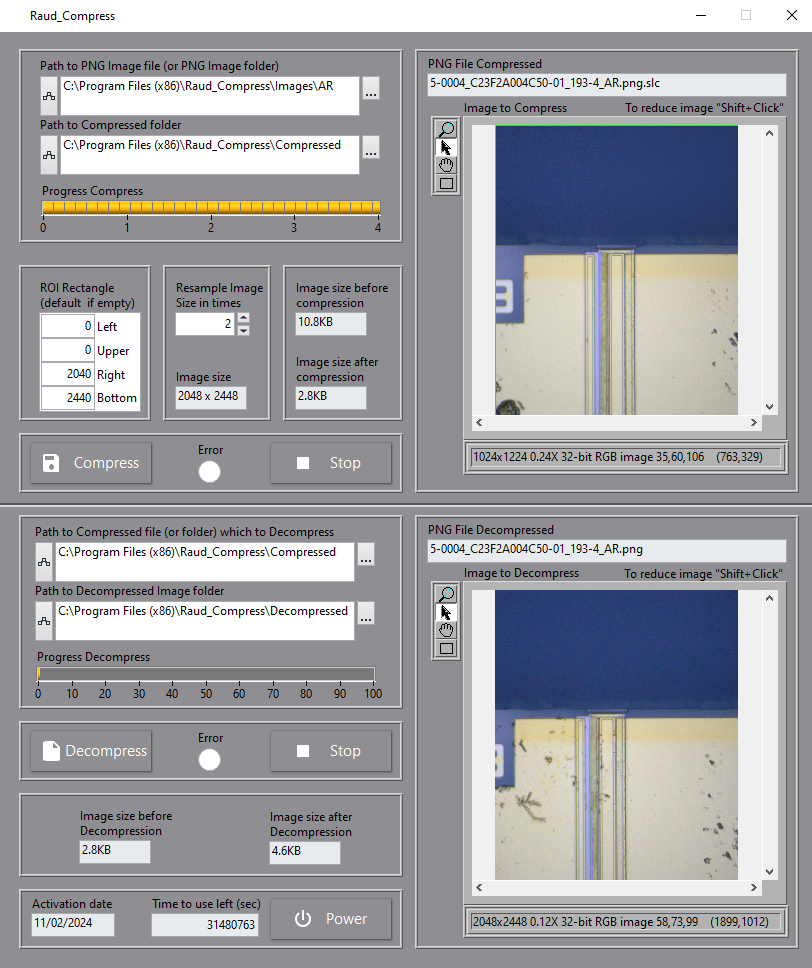
AK-RAUD PNG Compressor
AK-RAUD PNG Compressor is an application that compress PNG files. The current existed on the market applications including ZIP file compressor are not able to compress PNG files due to U32 specific image array arrangement. Even advanced convertion using U8 RGB arrays transformation just encrease the file waight. So, the AK-RAUD PNG Compressor is a unique opportunity to save up to 80% of the disc space by compressing PNG Images with no losing pixels or image quality. For those who is working with tonns of image files it is a solution to keep the HD/SSD in good shape. The Copressor may automatically grab just one file or files from the folder and compress all to the alocated directory. The compressor has the decompress mechanism that allows to decompress as one as ALL image files located in the pointed directory (folder).
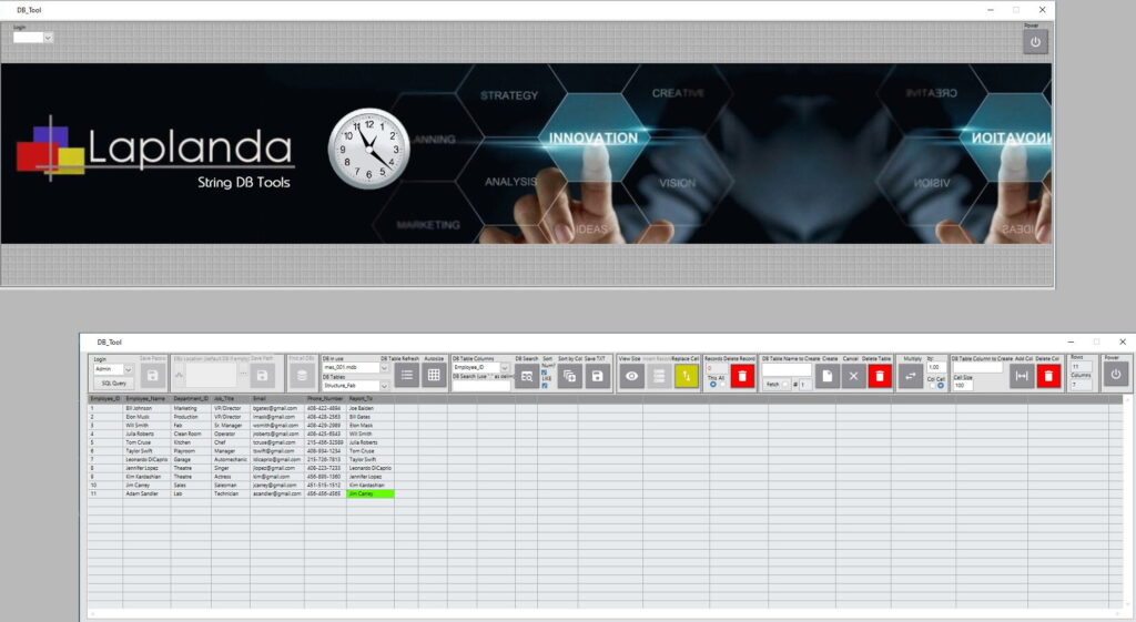
DATABASE TOOL
Laplanda String DB Tool is a database management tool that helps any small business efficiently organize its operations. Every small business needs to create and store information about employees, products, suppliers, transactions, accounting, salaries, expenses, and more. Laplanda String DB Tool combines all these functions.
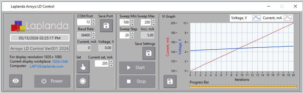
Laser Devices Current Control Tool for Arroyo instruments
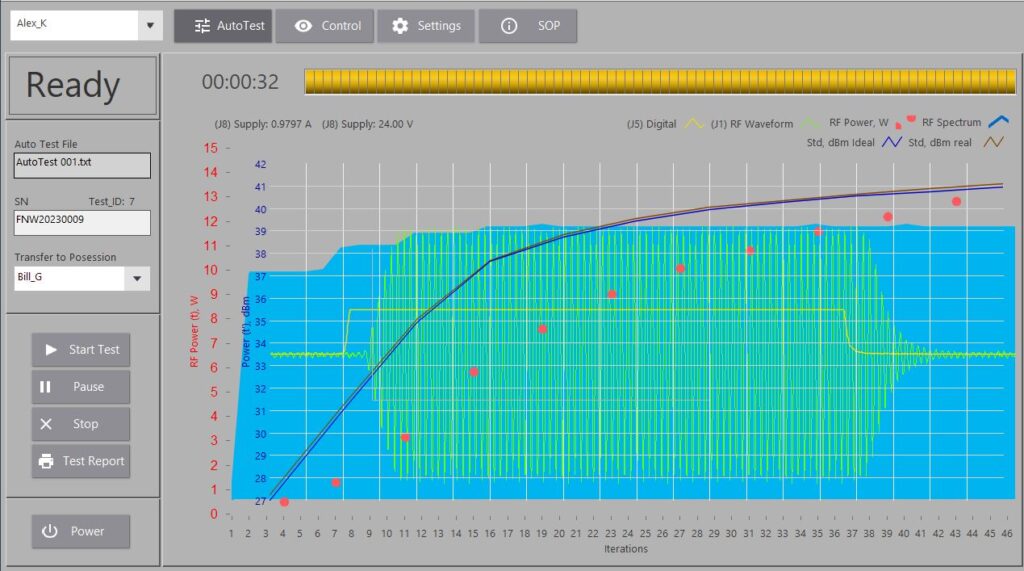
Laplanda_LD_Arroyo_Control is a Windows-based application developed for advanced control of Arroyo Laser Devices.
The software duplicates the functionality of the original Arroyo GUI while adding several enhanced automation and monitoring features. Users can perform automated current sweep operations between selected minimum and maximum current values with configurable iteration steps. The application provides a real-time VI (Voltage-Current) graph for accurate visualization of laser device behavior during operation. Raw measurement and graph data can be saved directly to CSV files for further analysis, documentation, or quality control processes. The interface is optimized for Full HD displays (1920×1080) and provides a clean, user-friendly control environment. Communication with the Arroyo instrument is handled through configurable COM port and baud rate settings for reliable serial connectivity. To reduce system resource usage, the software includes an intelligent standby mode with a 30-minute inactivity delay.The internal timing loop operates at 500 milliseconds, helping minimize CPU and RAM consumption during continuous operation. Laplanda_LD_Arroyo_Control is distributed as a Windows executable and installation package for fast and simple deployment on laboratory and production computers.
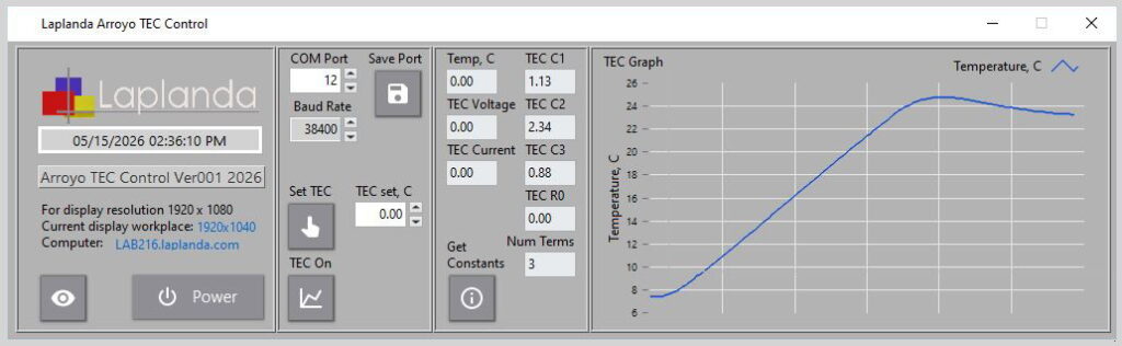
Laser Devices TEC Control Tool for Arroyo instruments
Laplanda_Arroyo_TEC_Control is a Windows-based application developed for monitoring and controlling Arroyo TEC (Thermoelectric Controller) devices through a simple and intuitive graphical interface. The software extends the functionality of the original Arroyo GUI by providing real-time TEC temperature visualization and live temperature graph monitoring. Users can configure COM port communication settings, control TEC output parameters, and monitor voltage, current, and TEC constants directly from the application. The application includes data acquisition features for accurate temperature tracking and supports stable long-term operation with optimized CPU and RAM usage. Laplanda_Arroyo_TEC_Control is distributed as a ready-to-install Windows package for laboratory, testing, and production environments requiring reliable TEC device management.